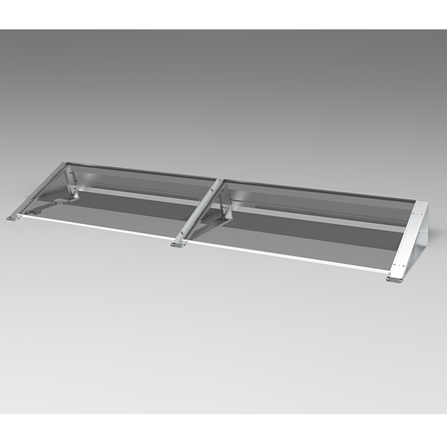
Commercial and residential flat roof solar projects carry unique, high-stakes challenges. Installers face immense wind uplift risks, stringent building weight limitations, and the critical need to preserve existing waterproof membranes. Selecting a highly reliable Solar Mounting System requires a delicate balance. You must weigh aerodynamic stability against long-term structural safety requirements. Unfortunately, buyers often encounter unverified, one-size-fits-all vendor claims. These generic solutions fail to address site-specific structural vulnerabilities. This creates substantial engineering risks for property owners.
This article provides a robust technical evaluation framework to help you navigate these complex decisions. We will show you how to assess mounting hardware viability and compare different structural approaches. You will learn practical strategies to mitigate installation risks and protect roof warranties effectively.
Key Takeaways
Stability on flat roofs is achieved through a calculated combination of aerodynamics, weight distribution, and strategic mechanical attachments.
A pure ballast solar mounting system is ideal for preserving roof integrity but requires rigorous structural engineering to ensure the roof can handle the added dead load.
Selecting a flat roof solar racking system requires evaluating site-specific wind zones, roof membrane compatibility, and third-party testing data (e.g., UL certifications and wind tunnel testing).
Protecting the existing roof warranty is just as critical as the racking system's warranty; improper installation can void both.
Before installing solar panels, engineers must evaluate the specific environmental forces acting upon the building. Flat roofs present unique aerodynamic and structural challenges. You cannot treat them like standard ground-mounted or pitched-roof installations.
Wind Uplift and Aerodynamics
Flat roofs generate complex wind turbulence. When wind strikes the vertical face of a building, it aggressively shoots upward. It then spills over the parapet edge, creating swirling vortices across the roof surface. Solar panels essentially act like large sails catching this turbulent air. This creates a powerful "sail effect" across your solar array. Mitigating this massive upward force represents the primary stability challenge for any rooftop design. If uplift forces exceed the downward weight of the equipment, the entire array can shift or detach.
Structural Load Capacities
Roofs only support a finite amount of weight. Structural engineers mandate a strict differentiation between dead loads and live loads. Dead loads include the constant, unchanging weight of the solar panels, concrete blocks, and the racking structure itself. Live loads fluctuate based on temporary environmental conditions. They include heavy winter snowfall, maintenance workers walking the array, and sudden seismic activity. You must calculate both load types together. The combined weight must never exceed the original structural limits of the building.
Water Pooling and Drainage
Despite their name, flat roofs are rarely perfectly flat. They rely on subtle pitches to direct rainwater toward internal drains or external scuppers. Poorly placed racking components easily block these natural drainage paths. This blockage leads to dangerous water accumulation. Standing water creates localized stress on roof trusses. Furthermore, continuous submersion accelerates the degradation of roofing membranes and metal racking components. You must carefully map water flow routes before approving a final layout.
Comparing Flat Roof Solar Racking System Categories
Engineers categorize flat roof mounting structures based on how they secure the array to the building. Each methodology offers distinct advantages. The optimal choice depends entirely on your specific site conditions.
Ballast Solar Mounting System
This approach relies entirely on gravity. A ballast solar mounting system uses heavy concrete blocks to weigh the structure down. It requires zero penetrations into the roof deck.
Mechanism: Installers place precision-calculated concrete blocks into designated mounting trays. This downward force resists wind uplift.
Best for: Concrete buildings featuring high reserve load capacity. It is also ideal for facilities holding pristine, strict roof warranties.
Limitations: This design is largely infeasible for high-wind hurricane zones or high-seismic regions without major modifications. It adds significant overall weight to the structure.
Mechanically Attached Systems
When weight limits prohibit concrete blocks, installers turn to physical anchors. These systems tie directly into the structural skeleton of the facility.
Mechanism: Installers physically bolt the mounting feet into the steel roof deck or underlying structural wooden joists.
Best for: Older buildings displaying low load-bearing capacity. They are also mandatory in locations facing extreme wind events.
Limitations: They present a high risk of catastrophic water leaks. Flashing and chemical sealing must be perfectly executed around every single penetration point.
Hybrid Systems
Hybrid setups offer a pragmatic middle ground. They merge the non-invasive nature of ballasting with the security of mechanical fasteners.
Mechanism: The design combines a primary ballasted base but utilizes minimal, strategic mechanical attachments at the array edges.
Best for: Commercial flat roofs requiring a delicate balance. They accommodate strict weight restrictions while meeting high wind resistance codes. Many engineers consider this the most reliable overarching choice.
System Category
Primary Stability Force
Roof Penetrations
Ideal Scenario
Pure Ballast
Gravity (Concrete Blocks)
None
High load capacity, low wind zones
Mechanically Attached
Physical Fasteners
High
Low load capacity, hurricane zones
Hybrid System
Combined Gravity & Fasteners
Low/Strategic
Moderate load capacity, high wind zones
Engineering Criteria for Maximum Stability
Choosing the right overarching category is only the first step. You must also evaluate the specific engineering features integrated into the hardware. Small design nuances dramatically alter stability.
Aerodynamic Wind Deflectors
Properly engineered systems utilize aerodynamic wind deflectors. Installers attach these solid metal shields to the northern edge of the solar panels (in the Northern Hemisphere). Properly angled deflectors actively alter wind flow over the array. Instead of allowing air to slip underneath the panels, the deflectors force the wind over the top. This dynamic action actively pushes the system down into the roof. It turns a potential destructive force into a stabilizing mechanism.
Tilt Angle Implications
Panel tilt angles require a strict trade-off analysis. You must balance potential energy yield against aerodynamic stability.
Low Tilt (5 to 10 degrees): These angles keep the panels tight to the roof surface. They significantly reduce wind drag. This allows for fewer concrete ballast blocks. However, they capture less winter sunlight and require more frequent manual cleaning due to poor self-cleaning slopes.
High Tilt (15+ degrees): Steeper angles maximize solar production. Unfortunately, they catch much more wind. This necessitates massive increases in ballast weight or structural penetrations.
Load Distribution & Footprint
A stable system must spread its weight safely across the roof surface. You must avoid dangerous point loads. A point load occurs when too much weight concentrates on a tiny surface area. Heavy, concentrated points can easily puncture underlying polyiso insulation boards. Good racking designs feature wide, elongated bases. These wide bases distribute the system weight broadly, preserving the structural integrity of the insulation underneath.
Material Integrity
Flat roofs create aggressive microclimates. Temperature swings are extreme, and standing water occurs frequently. You must compare material longevity carefully.
Extruded Aluminum: Highly resistant to rust. It maintains structural rigidity even after years of partial submersion in standing water. It forms a protective oxide layer naturally.
Galvanized Steel: Strong and rigid initially. However, the protective zinc coating can scratch during installation. Scratches expose raw steel to standing water, initiating rapid rust and structural failure.
Implementation Realities and Roof Protection
Hardware quality means very little if the execution damages the facility. Protecting the existing building envelope remains paramount during construction.
Membrane Compatibility & Slip Sheets
Roofs utilize various waterproofing membranes, including EPDM, TPO, and PVC. You cannot simply place metal racking feet or rough concrete blocks directly onto these surfaces. They cause mechanical chafing during thermal expansion. More dangerously, incompatible materials cause chemical degradation. For example, placing standard rubber pads on PVC roofs causes plasticizer migration, turning the roof brittle. You must use manufacturer-approved protective slip sheets. These sheets sit directly between the racking components and the roof. They prevent chemical reactions and absorb mechanical friction.
Navigating Roof Obstructions
Commercial roofs are incredibly crowded spaces. They house large HVAC units, plumbing vents, skylights, and parapet walls. A rigid, inflexible racking layout will inevitably fail here. A high-quality flat roof solar racking system must feature profound modularity. Installers must route the arrays safely around these obstacles. The system must accommodate broken rows and staggered layouts without compromising its interconnected structural integrity.
Installation Tolerances
We must acknowledge the harsh realities of contractor error. Systems requiring highly complex onsite assembly carry severe implementation risks. If a system demands dozens of tiny parts or highly precise torque specifications for every bolt, mistakes will happen. Under-torqued bolts vibrate loose over time. Over-torqued bolts strip aluminum threads, weakening the frame. The best mounting systems minimize loose components. They utilize pre-assembled hinges and standardize bolt sizes to reduce human error on the roof.
Evaluation Framework for Shortlisting Providers
Procurement teams need a rigid framework to evaluate vendors. Do not rely on marketing brochures. Demand hard engineering data before signing contracts.
Demand Wind Tunnel Testing Data
Basic engineering stamps are insufficient for flat roof aerodynamics. Reputable manufacturers invest heavily in boundary-layer wind tunnel testing. These tests simulate real-world turbulence passing over specific roof shapes. Vendors should readily provide these test reports. The data must explicitly prove their aerodynamic uplift coefficients. If a vendor cannot produce independent wind tunnel data, you should disqualify them immediately.
Code Compliance & Certification
Verify strict compliance with local and international structural codes. The mounting hardware must meet ASCE 7 standards for both wind uplift and seismic load limits. Additionally, the system must carry UL 2703 certification. UL 2703 evaluates the electrical grounding continuity and the mechanical loading limits of the entire mounting assembly. These certifications guarantee baseline safety thresholds.
Warranty Intersections
Commercial roof warranties are highly restrictive documents. You must ensure the mounting system manufacturer explicitly supports the specific roofing membrane currently in use. Furthermore, you must engage the original roofing manufacturer. Verify their engineers approve the solar layout, the slip sheet materials, and the flashing details. Improper installation actions will instantly void a multi-million-dollar commercial roof warranty.
Post-Sales Engineering Support
Assess the operational depth of the vendor. Do they just ship off-the-shelf hardware pallets? Or do they provide comprehensive post-sales engineering? A reliable vendor provides custom, site-specific layout designs. They deliver exact ballast calculations based on your local wind zone. They supply stamped structural drawings detailing where every single block belongs. This engineering support ensures long-term stability.
Conclusion
A stable flat roof solar installation represents a meticulous engineering partnership. You must perfectly align the building’s existing structural capacity with the mounting system’s aerodynamic design. Prioritize wind tunnel data, strict code compliance, and careful load distribution to prevent catastrophic failures. Protect your underlying assets by utilizing correct slip sheets and avoiding unnecessary roof penetrations.
Your immediate next step is clear. Before you shortlist specific mounting hardware or sign any procurement contracts, commission a formal structural engineering assessment of your facility. Determine your exact dead load capacity and local wind requirements first. This baseline data will dictate your entire hardware strategy.
FAQ
Q: How much weight does a ballast solar mounting system add to a flat roof?
A: A typical system adds between 3 to 6 pounds per square foot (PSF) to the roof structure. However, site specifics dictate the final number. High wind zones require heavier concrete blocks, pushing the weight closer to 6 PSF. You must obtain a structural engineering review to ensure your building can safely support this added dead load.
Q: Will a flat roof solar racking system void my roof warranty?
A: It can, but proper planning prevents this. You must use approved protective slip sheets under all racking feet and concrete blocks to prevent membrane chafing. Always coordinate directly with the original roofing manufacturer. Submit your layout plans to them for formal approval before beginning installation to maintain full warranty coverage.
Q: What is the best tilt angle for flat roof solar panels?
A: The standard recommended range is between 5 and 15 degrees. A 5-degree tilt significantly reduces wind drag, lowering your ballast weight requirements. A 15-degree tilt increases energy yield but catches more wind, requiring heavier ballast and wider row spacing to prevent shading. Most commercial projects settle on 10 degrees to balance yield and stability.
Q: Do I need roof penetrations if I live in a high-wind area?
A: Yes, generally. Pure ballast systems often fail structural calculations in hurricane zones. In these high-wind areas, hybrid systems featuring strategic mechanical attachments are typically required. These specialized anchors tie the array directly into the building's structural deck, preventing extreme wind uplift from displacing the panels.
We do research and trends of each country to give you the best possible product that will sell in your country. We have been the gold supplier of International Committee Red Cross since 2012.